MGF
Clutch Replacement Procedure
Author, Branko from
Australia, Ed.2,
2005 March, 9th.
written to the
MG Cars BBS
Clutch Replacement Procedure
This procedure is specifically for a MGF
1998 5 Speed manual with 1.8i engine.
I would think that this procedure could also be used on similar models.
This is a record of a step by step procedure that I followed to replace
my own clutch.
My friction plate had been worn down to the metal studs which heat scored
the flywheel.
The flywheel had to be removed to be machined, but, check if yours needs
to or not.
If not then, Removal: Steps 70 - 74 and Replacement: Steps 1 - 5 are not
required.
Please not that the clutch replacement is dangerous, so I adhered to recommended
safety precautions.
Please do the same if you attempt this procedure.
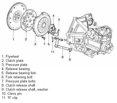
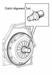
Here is a figure of the clutch to be replaced.
I basically used the workshop manual but removed/added steps as I required them.
A good set of garage tools will be required including some special tools that can be home made. Previous mechanical experience is recommended to perform this procedure.
“LHS” means “passenger side” if you have a RHD car.
I jacked the car up as far as I could so as to give me room underneath and used a sturdy box to stand on when working from above. I also used protective covers on the body panels so as to avoid scratches.
What I used:
Clear working area
Good lighting
MGF workshop manual for reference and diagrams
Engine hoist (or block and tackle)
2 sturdy car stands
2 Sturdy car jacks and/or hydraulic trolley jack
Metric Socket set (various sizes)
Metric Ring spanners (various sizes)
Tension/Torque wrench
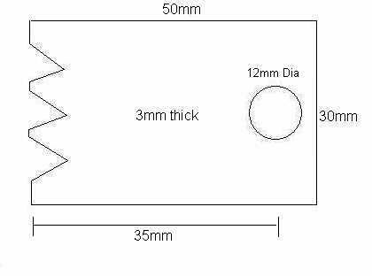
Flywheel locking tool (50x30x3)mm. With teeth cut out on one side to match
flywheel teeth and hole drilled on the other side for bolt.
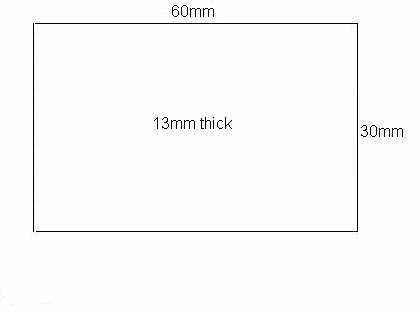
2 metal wedges (60x30x13)mm. I used a couple of pieces of metal taped together.
Set of screw drivers (Flat and Philip’s)
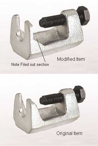
Ball
joint separating tool. I bought one and modified it to suit.
Clutch Aligning tool.
Other misc tools as required.
Air impact gun (very handy)
Removal
1. Disconnect battery earth lead.
2. Unscrew or retract aerial for ease of access.
3. Release soft top rear clips and secure rear window forward. (Tie with string)
4. Remove rear shelf carpet and remove engine cover (11x 10mm bolts).
5. Remove rear engine access grate in boot.
6. Loosen all rear wheel nuts (do not take remove yet).
7. Raise rear of car with hydraulic jacks and lower onto stands. (Wheels off ground).
8. Remove road wheels.
9. Use jacks and blocks of wood under lower suspension arms, raise rear hubs so that the car just lifts off the support stands and is fully supported on the jacks. (This compresses the upper suspension arms and removes pressure off the rubber stoppers in between the upper suspension arms and the subframes)
10. Remove rubber stoppers between upper suspension arms and subframes. (Use a stubby Philips head screwdriver).
11. Fit solid metal wedges between upper suspension arms and subframes.
12. Slowly lower rear hubs until car is fully on stands and then remove jacks.
13. Steps 6-12 may be performed on LHS then on RHS.
14. Remove air cleaner and large inlet hose.
15. Remove starter motor and disconnect 2 leads.
16. Drain gearbox oil and store in clean container. (Oil can be reused if in good condition)
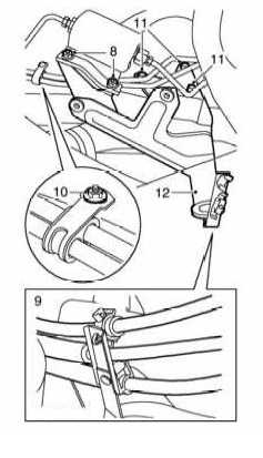
17. Remove 2 nuts securing fuel filter to air cleaner mounting bracket. (Fig-06 #8)
18. Release 2 hand brake cables and speedometer cable from clips on air cleaner mounting bracket. (Fig-06 #9)
19. Remove nut securing fuel pipe bracket to body. (Fig-06 #10)
20. Remove 3 bolts securing air cleaner mounting bracket to body. (Fig-06 #11)
21. Remove air cleaner mounting bracket. (Fig-06 #12)
22. Remove air cleaner bottom duct from resonator.
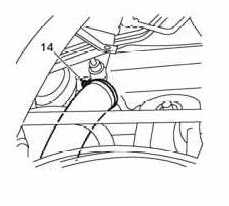
23. Loosen clip and cable tie and remove large air intake hose from resonator. (Fig-07 #14)
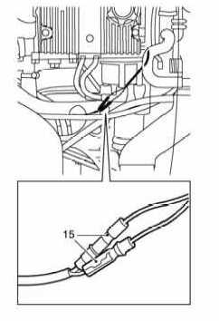
24. Disconnect 2 reverse light switch connections. (Fig-08 #15)
25. Remove ’R’ clip and clevis pin securing clutch slave cylinder push rod to release lever. (Fig-09 #16)
26. Remove push rod from slave cylinder.
27. Remove 2 bolts securing slave cylinder to mounting bracket. (Fig-09 #17)
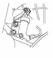
28. Release slave cylinder pipe from clip under bracket and move cylinder down under car.
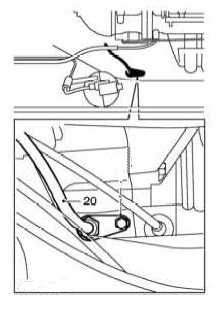
29. Release speedometer cable from gearbox. (Fig-10 #20)
30. Release clip securing starter motor lead to slave cylinder mounting bracket and position lead aside.
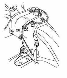
31. Remove 4 bolts securing clutch slave cylinder mounting bracket to gearbox. (Fig-11 #25)
32. Remove clutch slave cylinder mounting bracket. (Fig-11 #26)
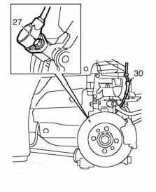
33. Remove bolt securing ABS speed sensors to both rear hubs. (Fig-12 #27)
34. Release ABS speed sensors from both hubs and collect spacers.
35. Release ABS sensor cable from 3 clips on both upper arms. (Fig-12 #30)
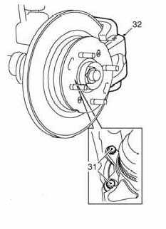
36. Remove 2 x 2 bolts securing both caliper carriers to hubs. (Fig-13 #31)
37. Move calipers aside and support on string so that both calipers are clear of the brake discs. (Fig-13 #32)
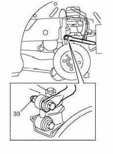
38.
Remove nuts and bolts securing anti-roll bar to LH and RH links. (Fig-14
#33) Then tie up anti-roll bar.
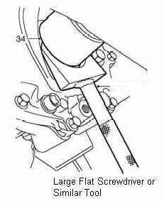
39. Release both drive shafts from gearbox using a large flat screwdriver. (Fig-15 #34)
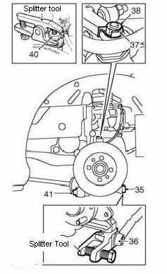
40. Remove nuts securing track control arms to both hubs. (Fig-16 #35)
41. Break track control arm joints using a ball joint separating tool. (Fig-16 #36)
42. Bend down lock tabs from both top ball joint nuts. (Fig-16 #37)
43. Remove nuts securing ball joints to upper arms. (Fig-16 #38)
44. Remove lock tabs.
45. Release taper joints from upper arms using a ball joint separating tool. (Fig-16 #40)
46. Remove bolts securing lower suspension arms to both hubs. (Fig-16 #41)
47. Remove both hubs from car complete with drive shafts.
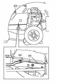
48. Remove 2 bolts securing plastic resonator box to body. (Fig-17 #43)
49. Release hydragas pipe from 3 clips on LH buttress. (Fig-17 #44)
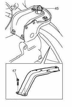
50. Remove nut and bolt securing LH engine mounting to buttress. Use ring spanner on top and socket from underneath. (Fig-18 #45)
51. Using a jack and block of wood (to protect sump), raise the engine.
52. Remove 4 bolts securing buttress to subframe. (Fig-18 #46)
53. Adjust height of gearbox and remove buttress. This takes some time as very little room to manoeuvre. Move buttress bottom out first towards firewall then push down then push top up and out.
54. Lower engine on jack until gearbox is fully resting on LHS subframe.
55. Adjust gearbox height as required, to remove plastic resonator box up and out.
56.
Remove
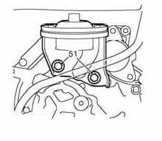
2 bolts securing LH engine mounting to gearbox (Fig-19 #51) and
remove the mounting.
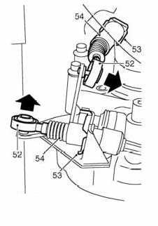
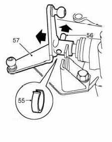
57. From under car, release both gear change cable ball joints from linkage. (Fig-20 #52) Spray WD40 first then pop out using a large flat screwdriver
58. Remove the 2 clips securing gear change cables to abutment brackets. These clips just slide out. (Fig-20 #53)
59. Release gear change cables from abutment brackets. (Fig-20 #54) Peel back the rubber cover then push cable back and slip out through cutting in bracket collar.
60. Remove circular clip retaining selector linkage roll pin. (Fig-21 #55)
61. Using a suitable punch or long bolt, drive out selector linkage roll pin. (Fig-21 #56)
62. Remove selector linkage from selector shaft. . (Fig-21 #57)
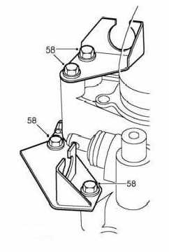
63. Remove 4 bolts securing the 2 gear change cable abutment brackets to gearbox and remove the brackets. . (Fig-22 #58)
64. Support gearbox and remove 7 bolts and 1 nut and bolt securing gearbox to engine. They are 3 x 17mm, 3 x 15mm and 2 x 13mm bolt heads.
65.
CAUTION: The gearbox is heavy.
CAUTION: During this procedure, keep the drive shaft horizontal to avoid
damaging the engine oil seal.
Raise engine so that the gearbox can be separated from it. Support the
gearbox.
With assistance, carefully release gearbox from engine. You may need to
use a large flat blunt screwdriver to prise away gearbox from engine.
Support gearbox either by a block and tackle suspended from and secured
to gearbox so that it does not spin around or support the gearbox from
underneath using a couple or jacks and again secure it so that the gearbox
does not spin around.
66. When gearbox is separated from engine, push the gearbox as far as it will go into the cavity where the resonator was. This will give about 6-8 inches of working room.
67. Remove the thrust (release) bearing from the bell housing. This slides out when the release forks swing out.
68. Remove 6 x 10mm bolts from the clutch pressure plate.
69.
Remove pressure plate and
clutch (friction) plate together. If required use a large a flat blunt
screwdriver to carefully prise the plate off from the dowels.
If the flywheel appears to be worn, scored, grooved, has heat marks, then
the surface of the flywheel will most likely need to be machined. In that
case, Proceed to step 70, Otherwise, removal is completed.
70. Attach flywheel locking tool to free hole on engine body.
71. Remove 6 bolts securing flywheeI
72. Loosen flywheel locking tool.
73. Remove flywheel.
74. Have the flywheel Machined.
Replacement
1. Fit flywheel. (Ensure dowels have been fitted to flywheel).
2. Fit 6 bolts to flywheel. (Hand tight)
3. Tighten flywheel locking tool.
4. Tighten 6 bolts on flywheeI. (tighten 85Nm in sequence)
5. Remove flywheel locking tool from engine body.
6. Fit pressure plate and clutch (friction) plate together to Flywheel. Ensure friction plate is facing correctly. Use a clutch tool for alignment.
7. Fit 6 bolts to clutch pressure plate.(Tighten to 25Nm in sequence)
8. Fit thrust bearing to bell housing forks. (Lubricate as per clutch kit instructions)
9. Push gearbox towards engine. CAUTION: The gearbox is heavy.
10. CAUTION: During this procedure, keep the drive shaft horizontal to avoid damaging the engine oil seal. Lower engine so that the gearbox can be aligned to it.
11. With assistance, carefully push gearbox to engine. Ensure gearbox does not spin around.
12. Fit 7 bolts and 1 nut and bolt and secure gearbox to engine. (Tighten: gearbox to engine 80Nm and gearbox to sump 45Nm)
13. Fit gear change cable abutment brackets to gearbox. (tighten 4 bolts to 45Nm)
14. Ensure selector linkage and shaft are clean, fit linkage to shaft.
15. Use a suitable punch or long bolt and drive in selector linkage roll pin.
16. Fit circular clip to retain selector linkage roll pin.
17. Clean gear change linkage and cable sockets. Fit gear change cables to abutment brackets through cutting in bracket collar. Push rubber cover in place.
18. Fit 2 clips and secure gear change cables to abutment brackets. These clips just slide in.
19. Apply grease to cable sockets and push on cable sockets to linkages.
20. Raise gearbox and fit LH engine mounting to gearbox with 2 bolts (tighten to 48Nm)
21. Raise gearbox as required and replace plastic resonator box but do not fit bolts at this stage.
22. Adjust height of gearbox and replace buttress. This takes some time as very little room to manoeuvre. (remove 3 clips from buttress to ease fitting)
23. Fit 4 bolts and secure buttress to subframe. (Tighten to 45Nm) (Refit 3 clips)
24. Lower engine and fit nut and bolt to secure LH engine mounting to buttress. Use ring spanner on top and socket from underneath. (tighten to 80Nm)
25. Fit hydragas pipe to 3 clips on LH buttress.
26. Fit 2 bolts and secure plastic resonator box to body. (Do not over tighten)
27. Lubricate differential oil seals.
28. Wipe and fit taper joints to upper arms.
29. Fit both hub assemblies to upper arms and engage both drive shafts to differential. They just push in with some force.
30. Fit lock washers to upper ball joint pins and tighten nuts to 54Nm.
31. Bend lock tabs up to lock both top ball joint nuts.
32. Test that drive shafts have engaged fully by pulling outward on drive shaft inboard joints.
33. Align both nubs to lower arms and fit bolts. (tighten to 100Nm)
34. Wipe tapers and seats of track control arms fit track control arm joints.
35. Fit nuts securing track control arms to both hubs. (tighten to 30Nm)
36. Untie anti-roll bar and fit nuts and bolts to anti-roll bar and LH and RH links.(tighten to 35Nm)
37. Untie calipers and fit to hub with 2 bolts (tighten to 85Nm).
38. Fit ABS sensor cable to 3 clips on both upper arms.
39. Clean ABS speed sensors, sensor spacers and mating faces on both hubs.
40. Fit ABS sensors to both rear hubs. (tighten bolts to 10Nm)
41. Fit clutch slave cylinder mounting bracket.
42. Fit 4 bolts to secure clutch slave cylinder mounting bracket to gearbox.
43. Fit clip securing starter motor lead to slave cylinder mounting bracket and position lead.
44. Fit speedometer cable to gearbox.
45. Move slave cylinder back up from under car and fit slave cylinder pipe to clip under bracket.
46. Fit slave cylinder to mounting bracket using 2 bolts. (tighten to 25Nm)
47. Clean clutch push rod and clevis pin and grease pin and end of rod.
48. Fit push rod to cylinder, align rod to clutch lever and fit clevis pin.
49. Fit ’R’ clip through clevis pin to secure.
50. Connect 2 reverse light switch connections.
51. Fit air intake hose to resonator and fit clip and cable tie.
52. Fit air cleaner duct (bottom) to resonator.
53. Fit air cleaner mounting bracket.
54. Fit 3 bolts to secure air cleaner mounting bracket to body.
55. Fit nut to secure fuel pipe bracket to body.
56. Fit 2 hand brake cables and speedometer cable to clips on air cleaner mounting bracket.
57. Fit 2 nuts to secure fuel filter to air cleaner mounting bracket.
58. Replace gearbox oil.
59. Fit starter motor and connect leads (tighten bolts to 80Nm)
60. Fit air cleaner and large inlet hose.
61. Use jacks and slowly raise rear hubs until car is just off the supporting stands.
62. Remove solid metal wedges from between upper suspension arms and subframes.
63. Fit rubber stoppers between upper suspension arms and subframes. (Use a stubby Philips head screwdriver).
64. Slowly lower rear hubs until car is fully supported on the support stands.
65. Fit road wheels and wheel nuts.
66. Raise rear of car with hydraulic jacks and remove stands and then lower to ground.
67. Tighten all wheel nuts.
68. Steps 61-67 may be performed on LHS then on RHS.
69. Fit rear engine access grate in boot.
70. Fit engine cover and 11 bolts and fit rear shelf carpet..
71. Lower the rear window and fit the rear window clips.
72. Fit aerial.
73. Connect battery earth lead.