The delayed Power Signal (updated 12.08.03/5)
Who did not already get angry about this ?
You switch off the ignition, but the windows are still open. Or you forgot
to open the boot with your additional fitted bootlid release kit. No Problem
our Friend Carl found a solution.:))
The main relay output signal is delayed for about 30 seconds until 1 1/2 minutes controlled by MEMS ECU. So enough time for young and old MGF Enthuthiasts to move the windows or open the boot. Carl sent the instruction by fax and eMail and I tried to build this web based instruction.
This instruction includes two ways to get the wiring done.
- Version for MGF with Aircon
- Version for MGF without Aircon
1. Introduction
When performing this alteration to the electrical system then be prepared
to put a standard flexible cable from the engine (MEMS Unit) to the front
of the car (dashboard fusebox). If no aircondition is installed, then
see below for usage of an existing not used cable of the aircon wiring.
This because Rover in their wisdom haven't fitted one single cable to
be used for this little extra equipment !
There are several rubber grommets in the engine bays walls etc. so its
not a big deal to put the wire in. But beware of future troubles (short
cuts!!) and stay away from any sharp objects that in time can cut thru
the cables isolation.
This description is valid for left hand drive cars. Some changes may exist
on right hand cars. Remove the negative lead from
the battery so all systems is safe to work on.
2. Required Parts
for the MGF with Aircon:
- app 4 meters of standard car wire (PVC isolated flexible) 0.75 or better
1.5 square mm.
in each case for both versions:
- 3 pcs of crimp connectors (pipes, for putting two wires together)
(can be replaced by other crimp connectors too)
- 2 pcs Diode. Type 1N400x- serie (i.e 1N4001)
- 1 pcs of cable bypass connector (blue coloured)
- app 40mm of shrink tubing to cover diodes and cable connectors
- cable tyes or similar to to attach cables securely
- Solder Iron , crimp tool.
- Printout of 'MEMS System' electrical diagram and 'Windows' electrical
diagrams
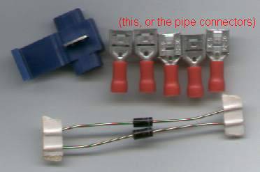 blue = bypass crimp connector
3. diode package preparation
- Take the 2 diodes and solder them together with short pcs of cable.
Attention on the polarity of the diodes !!
- Cover diodes and bare metal with shrink tubing.
- Result is a package with three cables coming out. A and B on one side,
C at the other side.
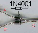
!!! drawn above not soldered and not isolated
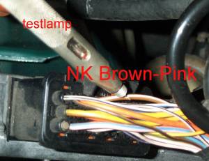
4. MEMS ECU Side wiring
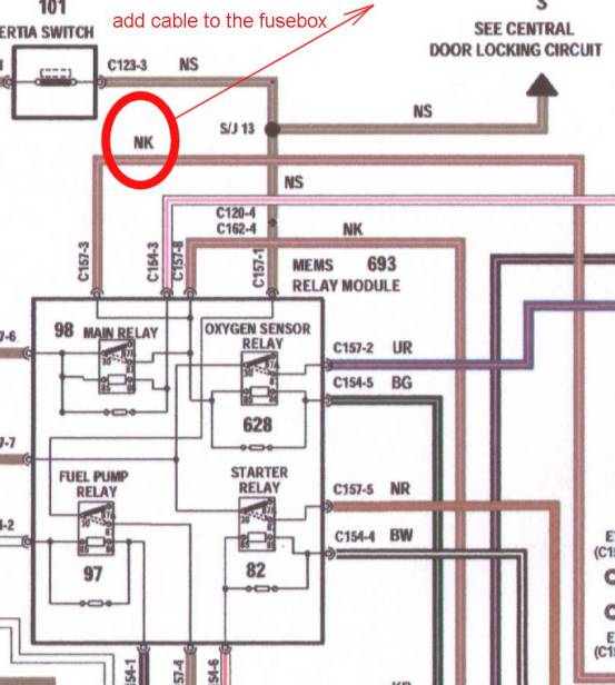
Look at the below drawn MEMS diagram for the main relay. The relais is
located below the ECU on the right hand side of the engine. There comes
out the cable marked with NK (Brown/Pink coloured). That one appears
at several places around the MEMS Unit in the engine compartment, i.e.
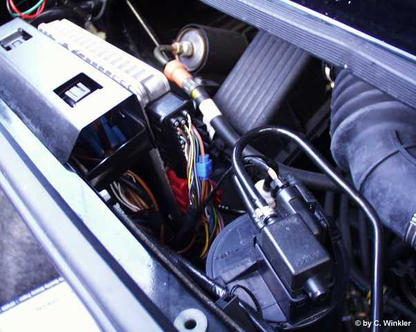
at the purge valve (see
picture)
MGF with aircon:
Connect at any place the 4m long cable to the Brown/Pink by use of the
blue coloured cable bypass connector.
Lead the cable up to the left upper side of the MGF and put it thru walls,
along the door sealing, under the carpet up in the footwell to the dashboards
fusebox.
MGF without Aircon:
make only a short connection between the (Brown/Pink) wire and
a not used wire at the ECU as described under issue 4.1
Principals explained at the ECU Main Relais diagram
This small copy of the MEMs wiring explains the rear located main relay,
located under the ECU and the brown-pink wire which leads the delayed
power signal to several actuators of the car. i.e to the purge valve.
| How to find the brown-pink anywhere for both versions | |
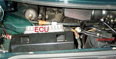 |
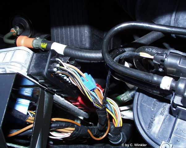
Overview picture (left hand arrow shows the position of the mainrelais connector, if the simple no aircon version |
 ECU
connector ECU
connector |
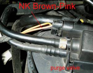 or here at the purge valve |
|
Location samples for the brown/pink delay signal
wire. At the Purge valve is the most easy to find location which
is recommended to be connected with a bypass crimp connector
|
|
Getting the Power delay signal from rear to the front of the car
4.1 Option for cars if an NO aircondition is installed .
It is possible on cars with NO installed aircondition to use an existing
cable between the footwell and the MEMS ECU unit. This makes work much
easier because no new long cable needs to be fitted. You only need to
make a short connection from the brown-pink to the following not use cable
at the connector behind the ECU.
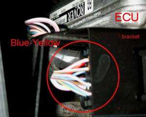
Locate the needed cable as follows at the rear:
When looking at ECU units left side you will see a black connector fastened to the black bracket which holds the ECU at th rear panel. Find the Blue Yellow wire. It has no connection on the right side of the connector, if no aircon is installed. This wire leads to the front under the dash board area to the not used but at each MGF existing white coloured multi connector for the aircon. We use this wire as substitute for the in other case to lead new long wire. you can cut it or use a bypass crimp connector to add a bypass wire to the brown-pink wire of the ECU.
Attach a connector or bypass and cable which is long enough to reach
the thin Brown Pink cable on the purge valve. This one is located slightly
to the right of the MEMS ECU unit. It is a black plastic container with
several hoses . On its top is a electric valve and 2 cables.
One Yellow Orange and the other is our wanted Brown Pink.
Locate the cable as follows at the front:
LHD cars Near the window lift relay at extreme left you will find a loose white coloured multi connector . This connector is supposed to go to the relaybox for the aircondition if fitted. Check the cables for the Blue Yellow. You can cut this wire or add a bypass crimp connector and wire of about 30cm lenght for the further works.
RHD cars you will find a loose white coloured multi connector
at the co-Drivers side, just near the upper hinge of the door behind the
footwell carpet. This connector is supposed to go to the relaybox for
the aircondition if fitted. Check the cables for the Blue Yellow. You
can cut this wire or add a bypass crimp connector and wire of about 1.50
m lenght for the further works. You need to lead this wire to the drivers
side where you find the window lift relay is at extreme right.
[Thnx fly to Paul Lane who gave this additional instruction for RHD cars
!! :) ]
Jump to 5. and leave out 4.2 if you have no aircon
connect a 4m long wire to the Brown-Pink wire and lead it to the front of the car to the fuse box.
(here the location of the brown-pink wire at the ECU) (c)picture courtesy Cyril Winkler
The way to the front leads below the left boot lid hinge to the rear left side of the cabin where the engine cover carpet is located. Find the oval grommet behind the caropet and lead the cable there to the cabin along the door frame to the fusebox.
5. Final front wiring for both options
Principals
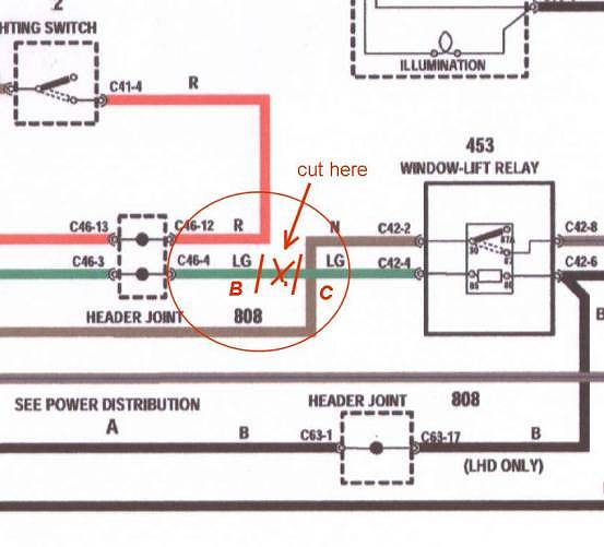
Look at the Windows electrical diagram. Find the 453 window lift relay.
Find cable LG (Light green) and cut it.
Connect point B of the diode package to the LG cable side which leads
to 'Header Joint 808'.
Connect 'C' of the diode to the other end of the cable (Window lift relay
control)
Attn.: For more additional actuators wich should be delayed in
power off, like a boot lid release solenoid you can conncect a relay coil
to terminal 'C' and lead the second terminal of the relais coil to 'ground'.
5.1 Location of the Window Lift Relay
Open up the cover for "Passenger Compartment Fusebox". Remove the cover
by loosening 2 screws at the hinge. Slight loosening is enough to draw
lid outward and removal. You can now see the fuses in a grey coloured
box and at the left corner 3 relays at the metal frame of the fuse box.
To get better access remove 2 nuts holding plastic fuseholder. Let this
unit hang down. You now can see the cables going to the 3 relays. The
upper relay is the Window lift relay. To this relay there are cables going
in following colours:
thin Black, thick brown, thick brown-blue and thin Light-Green.
It is the thin Light Green that is the one which shall be cut in a manner that enough cable exists at both ends for connection. The Light Green going to the relay connects to terminal "C" the other Light Green to terminal "B" of our diode package.
Connect side "A" of the diode package to the
- in case 4.1 lead bypass cable at the Blue Yellow, or
- in case 4.2 to the new cable.
All work at the fusebox is now completed. Reinstall the fuseholder and the lid.
6. Test
Testing for correct funktion.
Attach the ground wire back to the battery.
click several times on the Alarm Blippers 'close-button' to reset the
alarmsystem until the doors lock .
Start the engine and check that the windows can be opend and shut. Stop
the engine and release the ignition key. Check that the windows still
can be operated. Now the windows will be able to be operated for app.
30 seconds - sometimes up to 1,5 minutes.
Wait approx. 45 sec. MEMS should now have closed down and it should NOT
be possible to operate the windows.
6.1 Possible faults.
On some cars there is a power drain problem that looks as follows: When
car is left standing for around 10 days to 3 weeks there is no charge
left in the battery. This can be rather confusing as no light or other
current drawing device is on. Normal consumption for alarm etc. is very
low. (2..5mA?) The problem is that the MEMS unit never powers down!! This
means that the main relay and MEMS computer is running all the time! When
this happends also our delayed function for windows will never power down.
It is then possible to operate the windows at any time after shutoff off
engine. This is a MEMS-related problem NOT linked to above done alterations!
If this problem exists contact Your dealer.
This term is confusing on Dieters MGF because the delay time at his 96
MGF is recently 5 Minutes !?
7. Further extensions.
It is possible to connect an electric bootlid opener as well to this circuit.
Best done via a simple relay because this pull solenoid draws some heavy
current. Also be aware that upon operating such a device high back EMF-voltages
will be generated when switching. This back EMF is best dampend by a diode
across pullmagnet coil. Note the polarity of such a diode!
THAT IS WHAT ROVER SHOULD HAVE DONE FROM THE BEGINNING !!
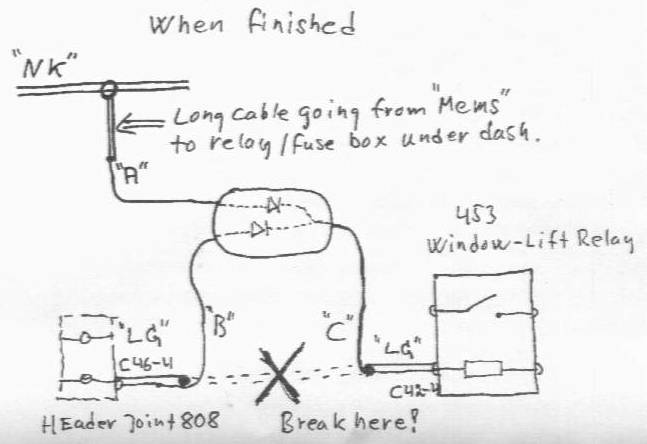
diagram for version with new long cable, similar valid if the existing
cable of an not installed aircon is used.