Picture sequence
Alarm System of the MGF (TF)
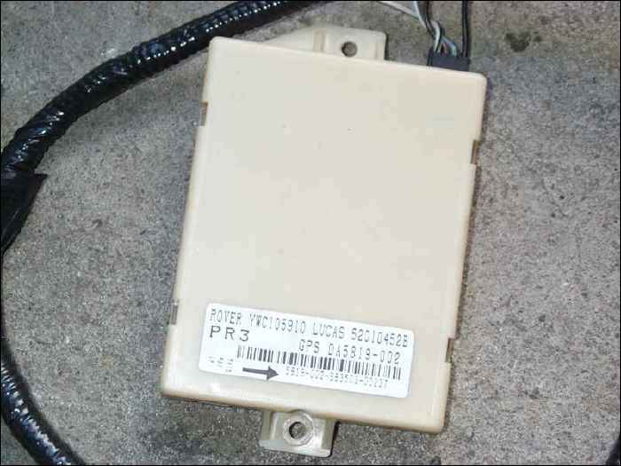
Lucas 5AS Security system http://www.alarmremotes.co.uk/new_page_4.htm
Landrover and Discovery, Mini/100/200/400/25/45/MGF. 433MHz YWX101220
(A) OR YWX101200
(Japanese Blipper version Part Number with different frequency 315MHz
is YWX 100870 )
Spare Blipper aswell available from
http://www.tech-tronics.net/mainsite/cart/remotes.htm or i.e. cheapest
from
http://www.hickleyvaltone.com/diagnostics/keys_list.php?manu=rover
http://www.remotekey.co.uk/cars/MG/mgf-mgtf/faq.asp
The EKA code could asked at your friendly dealer, or
try this service
See at Tom's site
http://homepage.swissonline.ch/TomsSeven/Main/Immobiliser_Logic.htm
See for manual action
http://www.mgcars.org.uk/cgi-bin/gen5?runprog=mgoc&a=&p=emg/immobilised.html
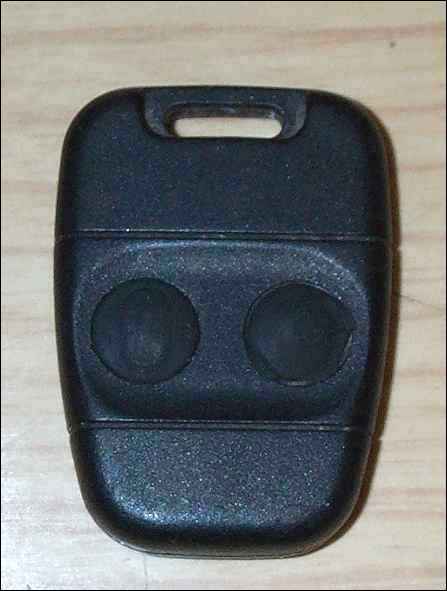
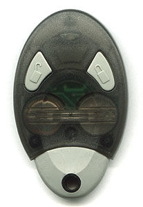
The key fob transmitter uses a 3V battery (No. 2032).
The MGF was delivered with 3TXA until about VIN 39xxx (app 1997)
and 3TXB since this time until the major change to a circular housing
transmitter with included 'Transponder'
The Transmitter 3TXC from a Land-Rover Discovery should work fine in the
system and should be much cheaper. 17TN as well.
Nissan Micra dated about 1996 uses also the 5AS Immobiliser with 2 button
blipper.
D.K.
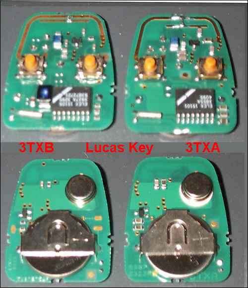
The difference between 3TXB and 3 TXA is not related to frequency.
David
from Alarm Remotes http://www.alarmremotes.co.uk/index.htm
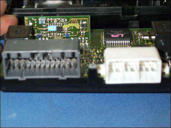
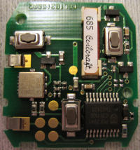
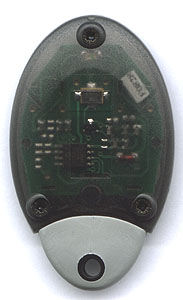
if you have a 1239 resonator (TO39-3 Case) then its 315Mhz. If you have
a 1207 resonator then its 433.92Mhz.
(Resonator, 2-Port, 180° Tol. = ±75 kHz)
RF Monolithics
http://www.rfm.com/products/data/rp1239.pdf
The only way to tell reliably what frequency the fob uses is by the number
on SAW resonator on the PCB. A lot of MGF's in the UK are 315 MHZ. But
the majority are 433.92Mhz.
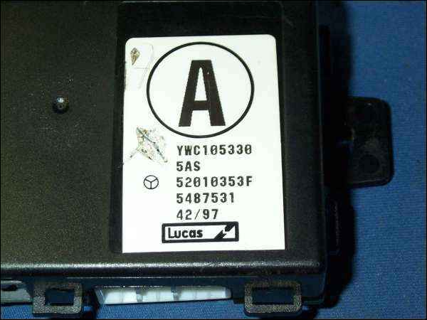
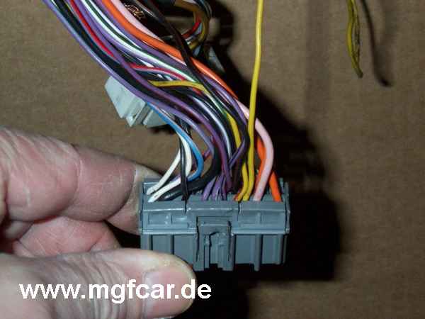
if you have a Lucas 5AS security ECU you will see on the label a black
25mm circle with a letter inside it.
Letters M/K/S/T all denote 315 mhz units. (There may be also be others)
Letters A/H/L/R all denote 433 mhz units.
______________________________________
(For the electronically challanged, its the small (TO39-3 Case)
round silver component on the battery side of the 3TXA fob).
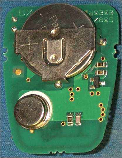
bottom LH, the frequency related electronic componentnt
Solution for the Alarm Blipper working range Problem ?
Carl , Sweden . Message to the MG Cars BBS on 1/10/1999 15:36
Hi all !
This is going to be a long thread about blipper system
for our beloved "F".
For receiver I will use "RX" and for transmitter "TX".
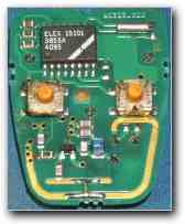
The keyholder contains the TX circuit and after doing some measurements on my 3TXA the following was found:
TX frequency. 433,895 MHz .
Modulation : Amplitude mod , (AM).
Output power at module before modulator : Approx. 1,5 mW at 3,1
Volt battery .
Type of antenna : Printed circuit loop tuneable with aid of small
soldered adjustable pin.
All in all output spectrum and power at distance of 10 meters measured
with L/4- whip at spectrum analyser showed fair enough signal to be accepted
of a not too deaf RX !
So what is the problem then?? Well, as stated some time ago in another
thread
- to make a small decent TX isn�t that big deal
- to make a good RX that works in todays polluted frequency spectrum is
another story !
Without having taken the RX apart (yet) I can bet that it is a simple
so called "superregenerative" receiver - known to radio amateurs as the
infamous "rushbox".
This is a cost effective way of solving the RX problem but it also generates
a few problems;
DESENSING: Nearby transmitters (not necessary spot on our frequency ) will make a not so good RX more deaf to wanted signals. This means we have to decrease distance to get any action at all.
PULLING: The nature of superreg. makes it fine for AM signals but if another signal off freq. is stronger this will make the RX "lock" onto this signal and further decrease in distance is needed.
SELECTIVITY : This is the costly thing, superreg. is bad news here.
FREQ: OFFSET : As RX and TX may have different temperatures we can have diff. in freq. This is today to some extent solved by the "SAW-resonator. At least the TX has a SAW.
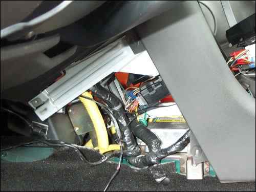
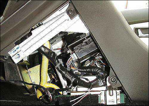
ANTENNAS: For the "bliper" there isn�t much of a choise, size demand small antenna and then for cost reasons printed circuit board loop resonator is the thing to go for. At RX end there is of course more space and normally the antennas on other manufact. are situated as free as possible. In outer mirror casing is one often used spot. In our case the yellow quarter-wave cable under dash is a bit displaced for optimunm reception ,even worse so when coiled together with all other cables !
So summing up I think that the main problem lies in the RX. Maybe a thin coaxial cable from the box and putting the antenna in a better place will give improvements , but this has to be found out. I will take a look at the RX this winter as car is on stands , my range is around 3-5 meters with straight RX-antenna - so not that impressed..... Regards , Carl.
REPLACEMENT PART
a replacementkit is availiable for that high value part. I think its
interesting for you (one of the oldest MGF) too: YWX101010 - repair kit
for the remote blipper. It contents the both casing? (housing) halfs and
the rubber button thing.
YWX101070L is the same part at Land Rover.(LR YWX101220 433 MHz complete
blipper)
(c) Carl G. B. Sweden, translated by Dieter Koennecke 02.10.99
Housing as Spare Part availiable:
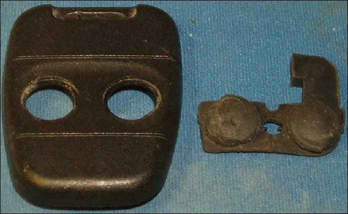
YWX101010 - repair kit for the remote blipper.
It contents the both casing halfs and the rubber button thing.
(The following steps 2 to 4, must be completed within 2 seconds, in order to induce the ECU to enter the self test mode.)
1) The vehicle must be in disarmed mode, unlocked and with the ignition switched off.
2) Lock the driver's door using the driver's door sill button.
3) Turn the ignition ON, OFF then ON again and leave it ON.
4) Unlock the driver's door using the driver's door sill button.
Confirmation that the test mode has been successfully entered is given by the horn sounding a short beep. Once in self test mode, the volumetric sensor (if fitted) is powered up and the vehicle is in an immobilised state.
If an ECU input is then seen to become active i.e. to go from an open circuit to a short circuit (or earthed) condition, the security LED will give a short flash to indicate this.
When the system is in the self test mode, operation of the appropriate switch by moving the associated panel or linkage will instigate the test on each of the following circuits;
1) Driver's door courtesy light switch.
2) Passenger door(s) courtesy light switch.
3) Bonnet open switch.
4) Boot open switch.
5) Driver's door key barrel switch. (Not on 100 models)
6) Boot key barrel switch (Not on 100 models)
7) Driver's sill button "up" switch.
8) Driver's sill button "down" switch.
Switch tests need not be made in any particular sequence and any or all may be tested as required.
Correct operation of the circuit being tested will be denoted by the
single flash of the security LED and the same circuit may be tested repeatedly
if necessary.
The self test mode can be terminated at any point by switching off the
ignition.
Failure of the ECU to enter the test mode will probably indicate that it is not receiving inputs from either the ignition power supply or the driver's door sill button switches.
VOLUMETRIC TEST
The test facility may also be used to check the operation of te volumetric sensor, either ultrasonic or Doppler microwave (if fitted), by performing the following;
With the system in self test mode and the remote handset previously programmed
and synchronised to the vehicle being tested, press the unlock button
once.
The ECU will now disregard inputs from it's associated switches, and will
instead, give a confirmation flash on the security LED to indicate that
the volumetric sensor has been triggered, the action of which can usually
be induced by waving a hand in front of the sensor.
The self test mode can be terminated by switching off the ignition.
http://www.alarmremotes.co.uk/new_page_4.htm
Paul Jameson B.Eng.
Electronics Engineer / Director
Avon Automotive Diagnostics Ltd
Tel +44 (0) 1789 450808
Fax +44 (0) 1789 773262
*Rov 2 Fob* model.
Can be adapted to the ECU without a visit to Testbook.